Building Haptic Face Interface for VR Headsets
Haptic Face Interface is the easiest SenseShift device you can build, and we recommend starting your journey with SenseShift with it! With 6 Haptic Feedback Points, you will deeply improve your immersion by feeling every touch and punch into your face.
Our Face Interface is supported by many games and works great with Standalone VR headsets, such as Meta Quest 2. It achieves it by providing a compatibility layer for bHaptics, making it possible to support bHaptics Tactal supported games.
Keep in mind that this guide is a work-in-progress and may not be complete, so you may need to do some additional research and problem-solving on your own.
If you need help or guidance along the way, be sure to consult with our community on Discord.
Prerequisites
- 3rd-party facial interface
- Soldering skills or will to learn
Build Guide
Step 1: Purchasing required components
A small variety of hardware components is required to build your DIY Haptic Face Interface. You can find a table with list of required components below. You'll also need some tools, such as Soldering Iron and knife or scalpel for device assembly.
| Component | Choice | Amount | Cost per | Approx. cost (w\ shipping) | Quick Link |
|---|---|---|---|---|---|
| ESP32-DevKitC V4 | 1 | $3.13 | ~$3.76 | AliExpress | |
| ULN2803 | 1 | $1.65 | ~$1.98 | AliExpress | |
| Coin Vibration Motor | 1 | $2.35 | ~$2.82 | AliExpress | |
| Half Sized Breadboard | 1 | $2.89 | ~$3.47 | AliExpress | |
| Jumper Wires | 1 | $1.09 | ~$1.31 | AliExpress | |
| Wires for soldering | 1 | $2.37 | ~$2.84 | AliExpress | |
| Facial Interface for Quest 2 | 1 | $29.00 | ~$34.80 | AliExpress |
You may need to adjust list according to your setup, e.g. changing face interface to a different model.
Step 2: Connect ULN2803
Insert your ULN2803 Darlington transistor arrays into the left-most part of your breadboard. Make sure, that indent on ULN2803 is on the left, and red line is on the bottom of your breadboard. Connect GND and 5V wires according to diagram below.
| Wiring Diagram | Photo |
|---|---|
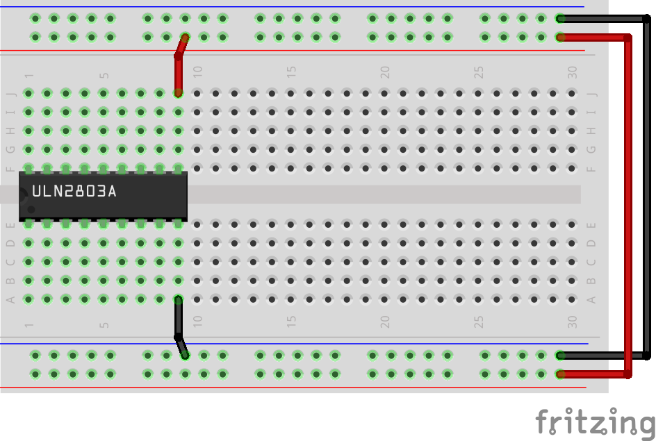 |  |
Step 3: Connect ESP32
Insert your ESP32 into the right-most part of your breadboard. Make sure, that you have a single row of non-obstructed below your ESP32 to connect wires later. Connect 5V pin with red line and GND pin with blue line with jumper wires.
| Wiring Diagram | Photo |
|---|---|
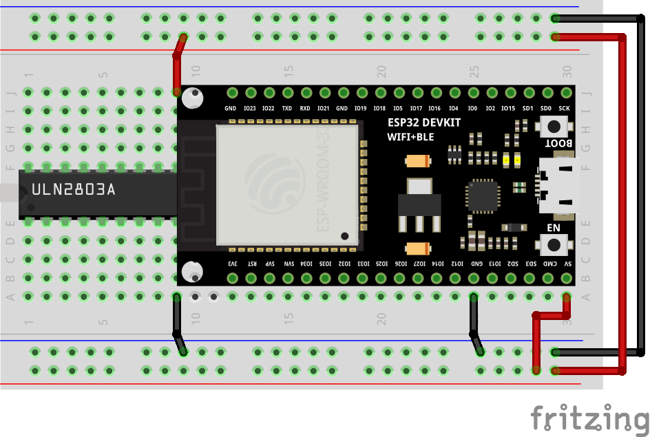 |  |
Connect pins IO14, IO27, IO26, IO25, IO33, IO32 with your ULN2803 with jumper wires array as per diagram below.
| Wiring Diagram | Photo |
|---|---|
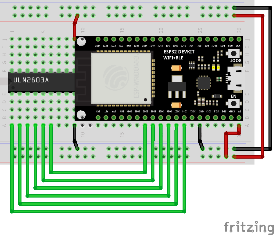 |  |
Step 4: Wire vibration motors
Solder jumper wires to your vibration motors, than connect them as per diagram below.
| Wiring Diagram | Photo |
|---|---|
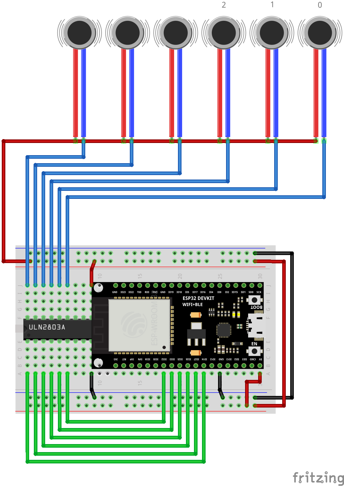 |  |
You'll need to make cuts in your Face Interface replacement. Make evenly-spaced cuts with knife to fit vibration motors in face pad (you can find image with motor locations below). Alternatively, you can attach motors with tape, if you do not feel like damaging your face interface.
| Motor Placement | Photo |
|---|---|
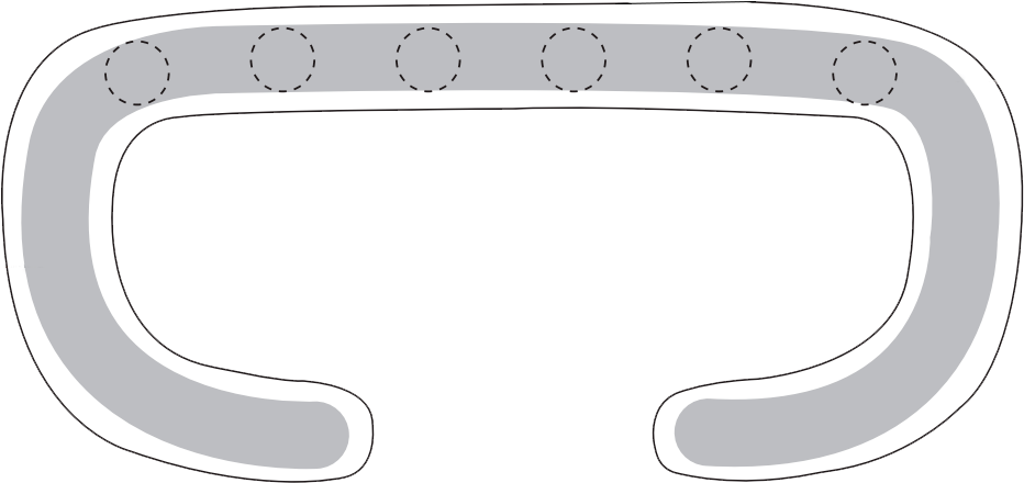 |  |
Step 5: Flash firmware
Use any of our Firmware Flashing methods and flash Face Interface (Tactal) firmware.
Final Result
Final Wiring Diagram